
Articles Resistor Basics
Resistor Packing Specification DIP SMD Resistor Sizes and Packages
Resistor Packing Specification
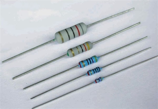
Resistor packages can be divided into two categories: Through-Hole Mount and Surface Mount.
Through-Hole Mount or DIP. The volume of the component is large, and the circuit board must be drilled to install the component. After the drilling is completed, the component is inserted, and then the tin furnace or tin spraying (also hand soldering) is costly.
Surface Mount or SMD. This kind of component does not need to be drilled, use a steel film to pour the semi-melted solder paste into the circuit board, and then put the SMD component on it. Solder on the circuit board. The volume of each type of resistor is also different, and the power characteristics are different. Generally, the larger the volume, the greater the power.
【Resistor Sizes and Packages】
DIPResistors
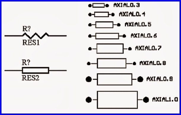
DIP Resistorspackage is in the form of AXIAL-xx. The xx behind AXIAL means the pad center spacing is xx inches. This size is actually slightly larger than the resistor itself. Common packages include AXIAL-0.3, AXIAL-0.4, and AXIAL- 0.5, AXIAL-0.6, AXIAL-0.7, AXIAL-0.8, AXIAL-0.9, AXIAL-1.0. Such as AXIAL-0.3, the pad center distance is 0.3 inches (7.6mm).
【DIP Resistor Packages】

【DIP Resistor Size】
AXIAL RESISTORS
AXIAL is a package of DIP resistors and is also used for devices such as inductors. The following number refers to the distance between the two pads.
AXIAL-0.3 low-power in-line resistance (1/4W); ordinary diode (1N4148); color ring inductor (10uH)
AXIAL-0.4 1A diode for rectification (1N4007); 1A Schottky diode for switching power supply (1N5819); transient protection diode
AXIAL-0.8 high-power in-line resistance (1W and 2W)
SMD RESISTORS:
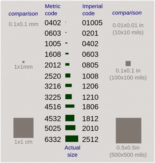
There are 9 common packages of chip resistors, which are represented by two size codes. One size code is an EIA (American Electronics Industry Association) code represented by a 4-digit number. The first two digits and the last two digits indicate the length and width of the resistor, in inches. The 0603 package we often talk about refers to the inch code. The other is the metric code, which is also represented by 4 digits, and its unit is millimeters. The following table lists the relationship between the imperial and metric system of the chip resistor package and the detailed dimensions:
【Chip Resistor】
Precision and resistance of chip resistors
The resistance error accuracy of the chip resistor has ±1%, ±2%, ±5%, ±10% accuracy,
J-means that the accuracy is 5%,
F- means that the accuracy is 1%.
T-means taping packaging
Resistance range from 0R-100M
Characteristics of chip resistors
1.Small size and light weight;
2.Adapt to reflow soldering and wave soldering;
3.Stable electrical performance and high reliability;
4.The assembly cost is low, and it is matched with the automatic placement equipment;
5.High mechanical strength and superior high frequency characteristics.
【SMD Resistor Size】
Resistor packages can be divided into two categories: Through-Hole Mount and Surface Mount.
Through-Hole Mount or DIP. The volume of the component is large, and the circuit board must be drilled to install the component. After the drilling is completed, the component is inserted, and then the tin furnace or tin spraying (also hand soldering) is costly.
Surface Mount or SMD. This kind of component does not need to be drilled, use a steel film to pour the semi-melted solder paste into the circuit board, and then put the SMD component on it. Solder on the circuit board. The volume of each type of resistor is also different, and the power characteristics are different. Generally, the larger the volume, the greater the power.
【Resistor Sizes and Packages】
DIPResistors
DIP Resistorspackage is in the form of AXIAL-xx. The xx behind AXIAL means the pad center spacing is xx inches. This size is actually slightly larger than the resistor itself. Common packages include AXIAL-0.3, AXIAL-0.4, and AXIAL- 0.5, AXIAL-0.6, AXIAL-0.7, AXIAL-0.8, AXIAL-0.9, AXIAL-1.0. Such as AXIAL-0.3, the pad center distance is 0.3 inches (7.6mm).
【DIP Resistor Packages】
【DIP Resistor Size】
| Power (watt) | Body Length (I) (mm) | Body diameter (d) (mm) | Lead diameter (da) | Lead length (a) mm | AXIAL | Pad center distance |
| 1/8W | 3.5±1.0 | 1.8±0.5 | 0.40±0.05 | 28±3.0 | AXIAL-0.3 | 7.6mm |
| 1/6W | 3.5±1.0 | 1.8±0.5 | 0.40±0.05 | 28±3.0 | ||
| 1/4W | 6.0±1.0 | 2.3±0.5 | 0.40±0.05 | 28±3.0 | AXIAL-0.4 | 10.2mm |
| 1/2W | 9.0±1.0 | 3.2±0.5 | 0.50±0.05 | 28±3.0 | AXIAL-0.5 | 12.7mm |
| 1W | 11.0±1.0 | 4.5±0.5 | 0.78±0.05 | 35±3.0 | AXIAL-0.6 | 15.2mm |
| 2W | 15.0±1.0 | 5.0±0.5 | 0.78±0.05 | 35±3.0 | AXIAL-0.8 | 20.3mm |
| 3W | 17.0±1.0 | 6.0±0.5 | 0.78±0.05 | 35±3.0 | AXIAL-1.0 | 25.4mm |
| 5W | 24.0±1.0 | 8.0±0.5 | 0.78±0.05 | 30±3.0 | AXIAL-1.2 | 30.5mm |
AXIAL RESISTORS
AXIAL is a package of DIP resistors and is also used for devices such as inductors. The following number refers to the distance between the two pads.
AXIAL-0.3 low-power in-line resistance (1/4W); ordinary diode (1N4148); color ring inductor (10uH)
AXIAL-0.4 1A diode for rectification (1N4007); 1A Schottky diode for switching power supply (1N5819); transient protection diode
AXIAL-0.8 high-power in-line resistance (1W and 2W)
SMD RESISTORS:
There are 9 common packages of chip resistors, which are represented by two size codes. One size code is an EIA (American Electronics Industry Association) code represented by a 4-digit number. The first two digits and the last two digits indicate the length and width of the resistor, in inches. The 0603 package we often talk about refers to the inch code. The other is the metric code, which is also represented by 4 digits, and its unit is millimeters. The following table lists the relationship between the imperial and metric system of the chip resistor package and the detailed dimensions:
【Chip Resistor】
Precision and resistance of chip resistors
The resistance error accuracy of the chip resistor has ±1%, ±2%, ±5%, ±10% accuracy,
J-means that the accuracy is 5%,
F- means that the accuracy is 1%.
T-means taping packaging
Resistance range from 0R-100M
Characteristics of chip resistors
1.Small size and light weight;
2.Adapt to reflow soldering and wave soldering;
3.Stable electrical performance and high reliability;
4.The assembly cost is low, and it is matched with the automatic placement equipment;
5.High mechanical strength and superior high frequency characteristics.
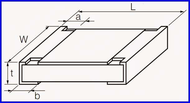
【SMD Resistor Size】
| (inch) | (mm) | (L) (mm) |
(W) (mm) |
(t) (mm) |
a (mm) |
b (mm) |
Power |
| 0201 | 0603 | 0.60±0.05 | 0.30±0.05 | 0.23±0.05 | 0.10±0.05 | 0.15±0.05 | 1/20W |
| 0402 | 1005 | 1.00±0.10 | 0.50±0.10 | 0.30±0.10 | 0.20±0.10 | 0.25±0.10 | 1/16W |
| 0603 | 1608 | 1.60±0.15 | 0.80±0.15 | 0.40±0.10 | 0.30±0.20 | 0.30±0.20 | 1/10W |
| 0805 | 2012 | 2.00±0.20 | 1.25±0.15 | 0.50±0.10 | 0.40±0.20 | 0.40±0.20 | 1/8W |
| 1206 | 3216 | 3.20±0.20 | 1.60±0.15 | 0.55 |